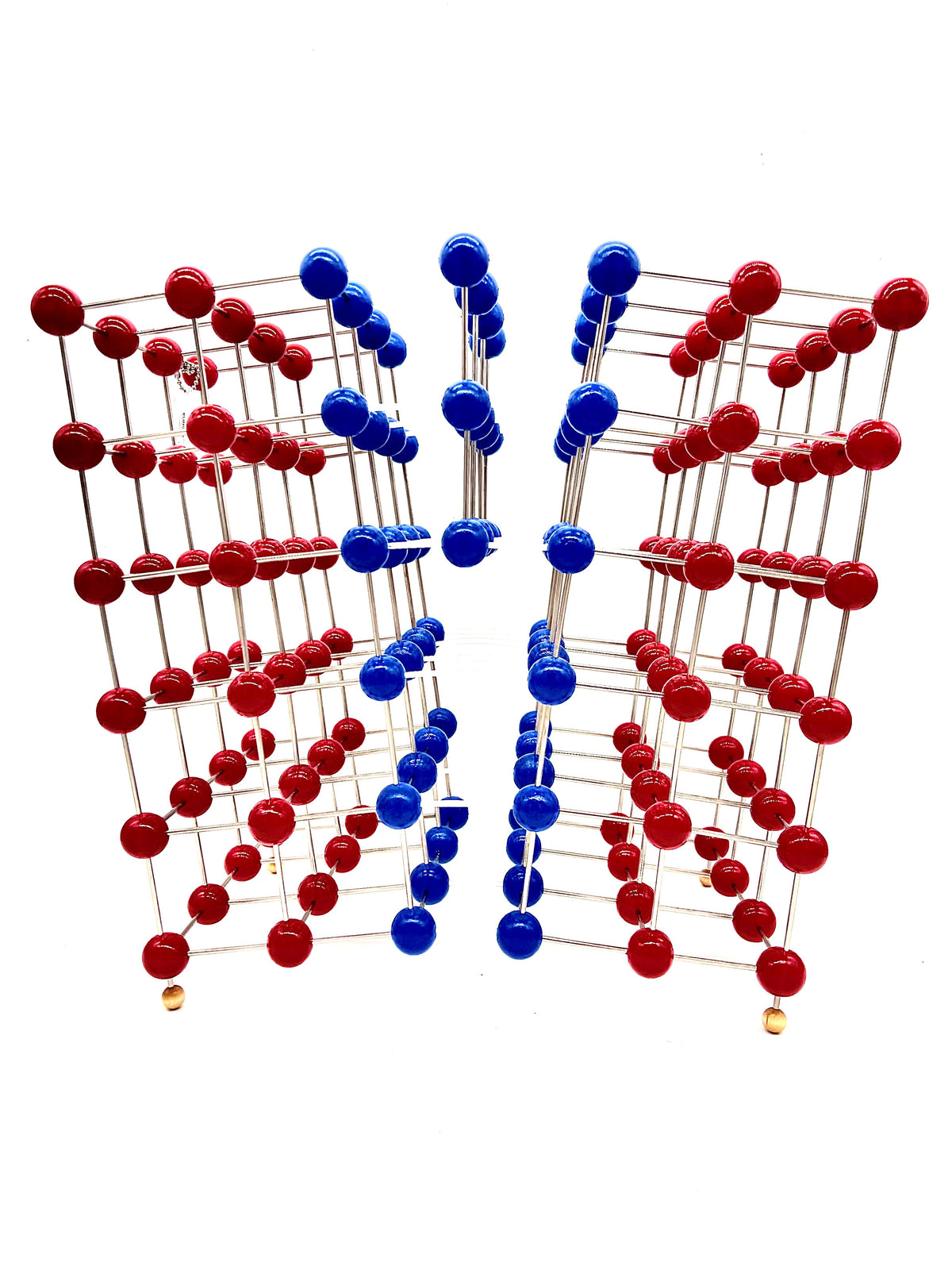
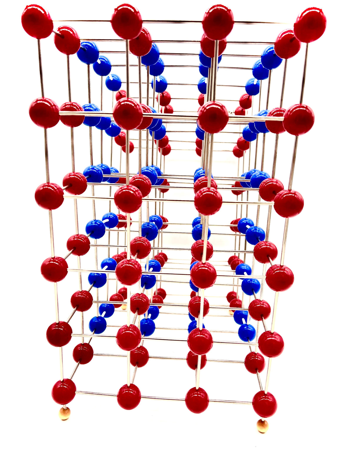
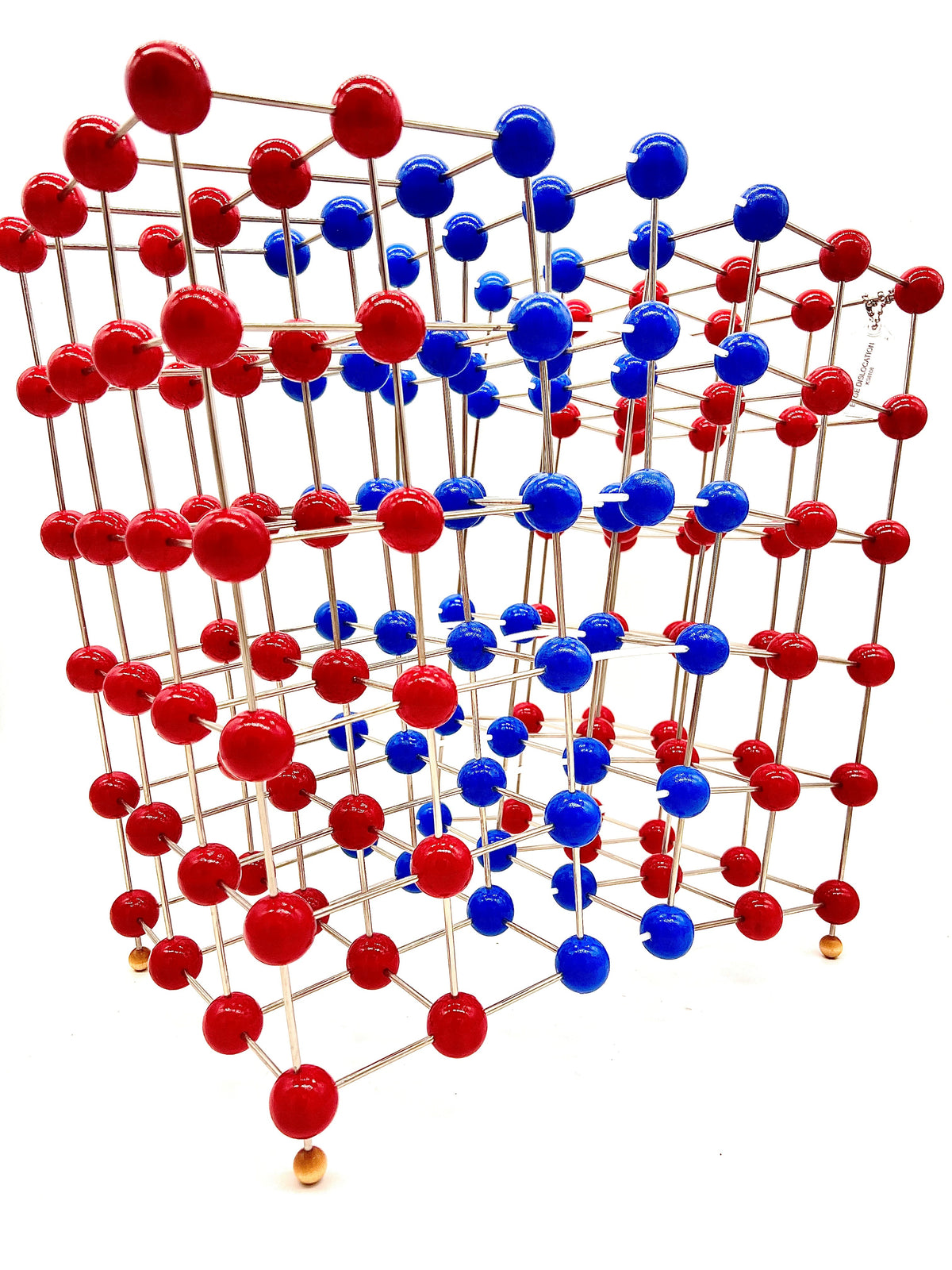
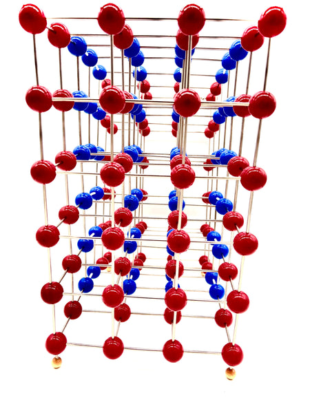
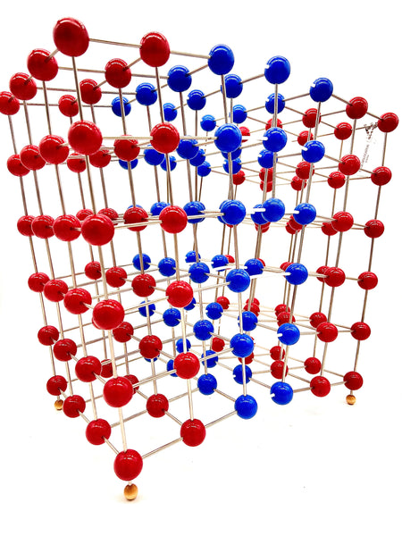
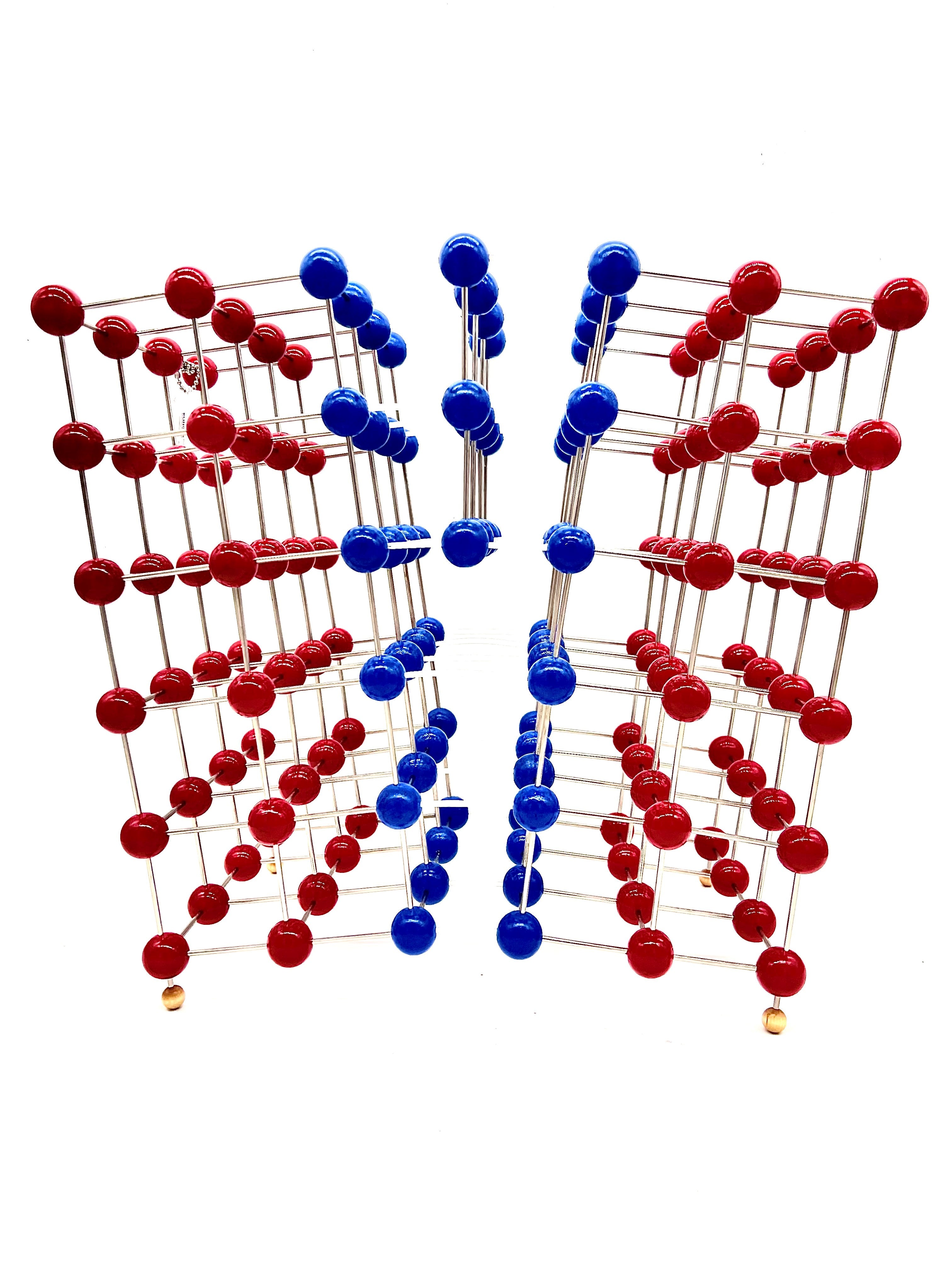
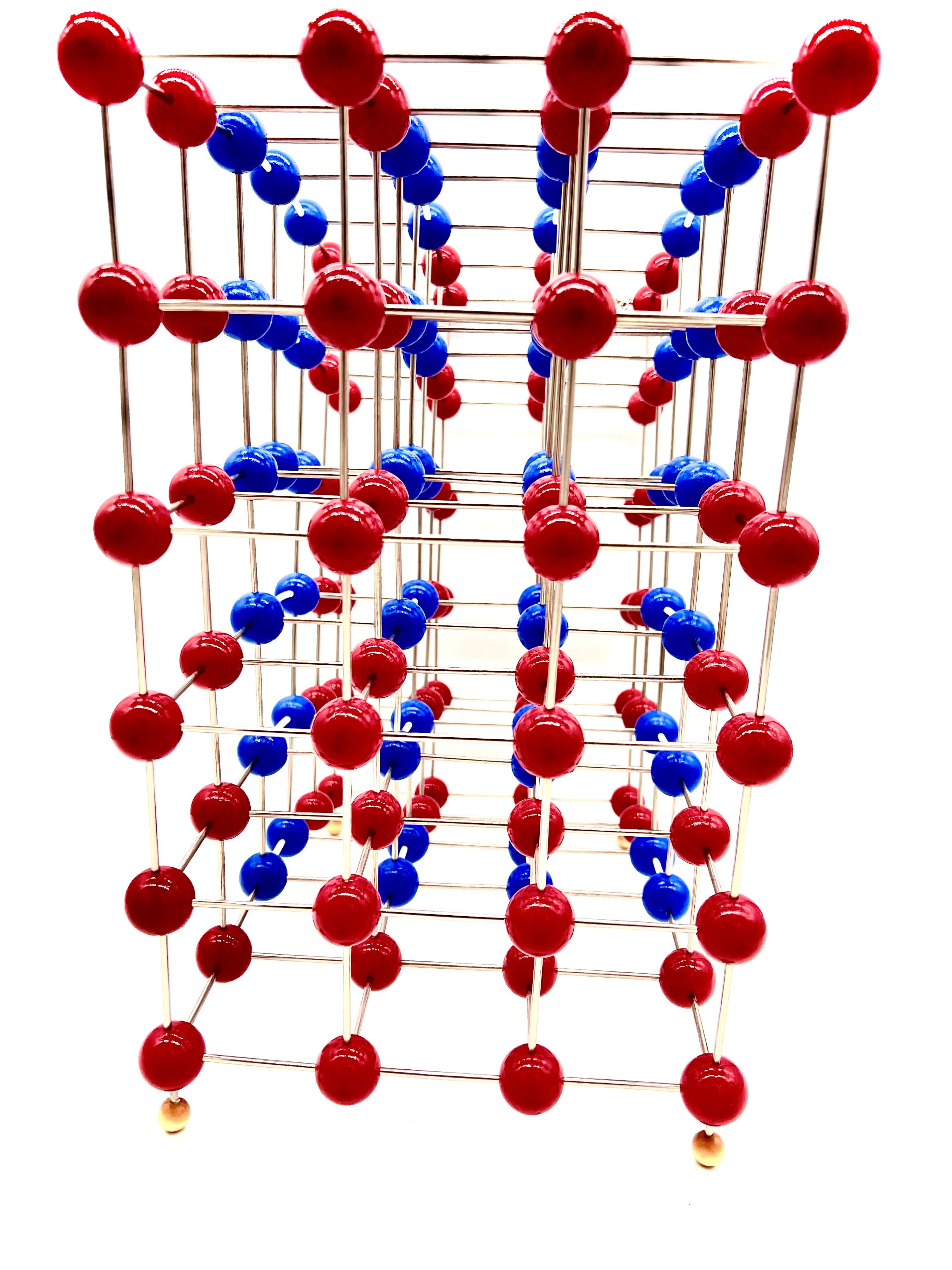
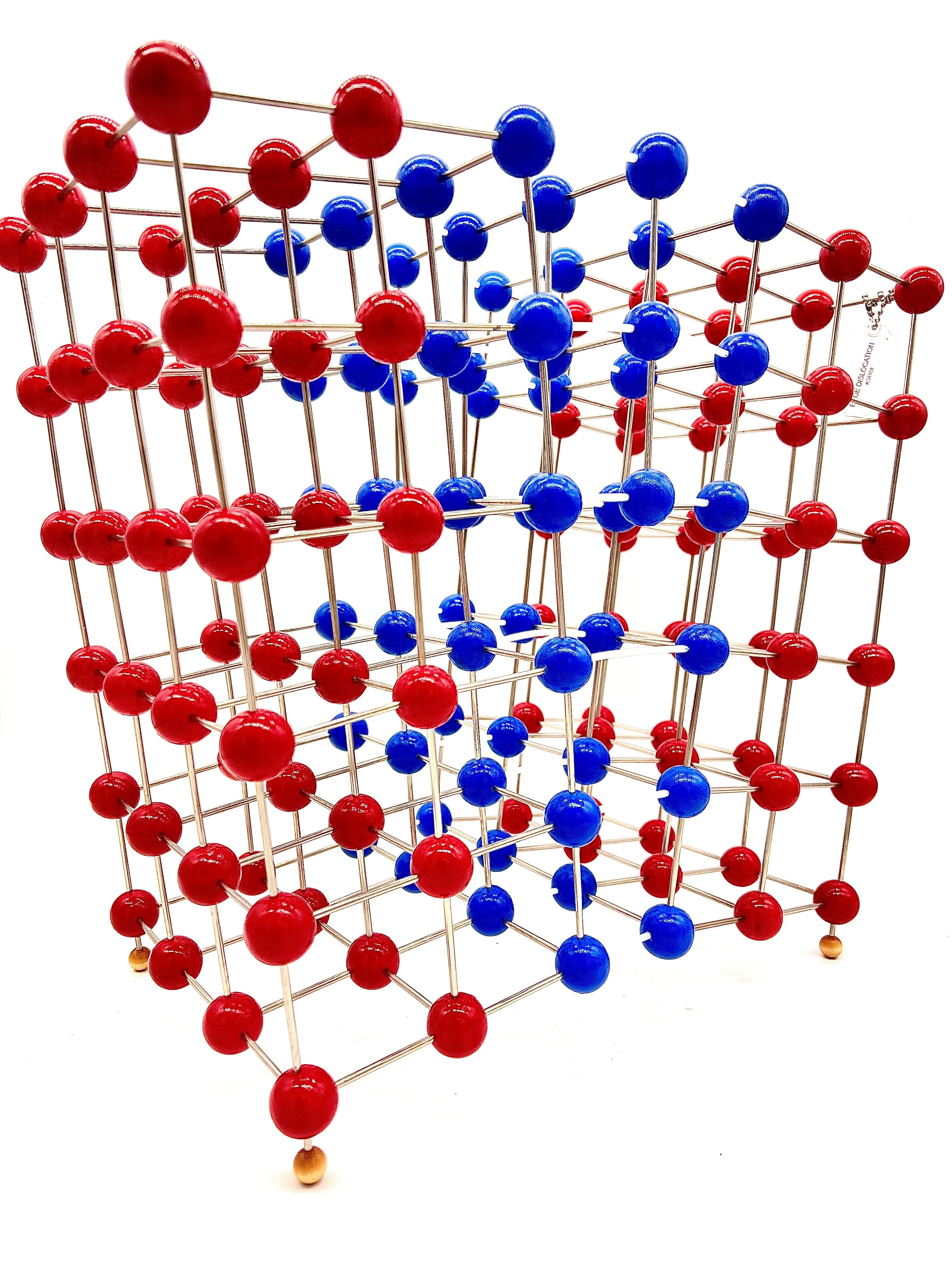
KS8108 Edge Dislocation Molecular Model
Couldn't load pickup availability
Edge Dislocation Molecular Model
In materials science, a dislocation is a crystallographic defect, or irregularity, within a crystal structure. The presence of dislocations strongly influences many of the properties of materials. The theory describing the elastic fields of the defects was originally developed by Vito Volterra in 1907, but the term 'dislocation' to refer to a defect on the atomic scale was coined by G. I. Taylor in 1934. Some types of dislocations can be visualized as being caused by the termination of a plane of atoms in the middle of a crystal. In such a case, the surrounding planes are not straight, but instead they bend around the edge of the terminating plane so that the crystal structure is perfectly ordered on either side. The analogy with a stack of paper is apt: if half a piece of paper is inserted in a stack of paper, the defect in the stack is only noticeable at the edge of the half sheet.
There are two primary types: edge dislocations and screw dislocations. Mixed dislocations are intermediate between these.
Two main types of dislocation exist: edge and screw. Dislocations found in real materials typically are mixed, meaning that they have characteristics of both.
Mathematically, dislocations are a type of topological defect, sometimes called a soliton. The mathematical theory explains why dislocations behave as stable particles: they can be moved around, but they maintain their identity as they move. Two dislocations of opposite orientation, when brought together, can cancel each other, but a single dislocation typically cannot "disappear" on its own.
A crystalline material consists of a regular array of atoms, arranged into lattice planes (imagine stacking oranges in a grocery, each of the trays of oranges are the lattice planes). One approach is to begin by considering a 3D representation of a perfect crystal lattice, with the atoms represented by spheres. The viewer may then start to simplify the representation by visualizing planes of atoms instead of the atoms themselves.
An edge dislocation is a defect where an extra half-plane of atoms is introduced mid way through the crystal, distorting nearby planes of atoms. When enough force is applied from one side of the crystal structure, this extra plane passes through planes of atoms breaking and joining bonds with them until it reaches the grain boundary. A simple schematic diagram of such atomic planes can be used to illustrate lattice defects such as dislocations. (Figure B represents the "extra half-plane" concept of an edge type dislocation). The dislocation has two properties, a line direction, which is the direction running along the bottom of the extra half plane, and the Burgers vector which describes the magnitude and direction of distortion to the lattice. In an edge dislocation, the Burgers vector is perpendicular to the line direction.
Edge dislocations
The stresses caused by an edge dislocation are complex due to its inherent asymmetry. These stresses are described by three equations: 


where μ is the shear modulus of the material, b is the Burgers vector, ν is Poisson's ratio and x and y are coordinates.
These equations suggest a vertically oriented dumbbell of stresses surrounding the dislocation, with compression experienced by the atoms near the "extra" plane, and tension experienced by those atoms near the "missing" plane.
This model is hand made in the USA by Klinger Educational Products. This is a permanent structure. We only use grade A materials. The 1 inch balls are made of hard Maplewood that includes an enameled painted finish. Polished steel rods are used to connect the wooden balls together.
Edge Dislocation contains 156 - 1 inch balls.


